RAB Lighting 26W LED Wallpack Installation Instructions


JUNCTION BOX MOUNT FOR CONDUIT For use on applications where conduit wiring is needed.

1. Loosen and remove (4) Lens Screws.  Remove Door.  
2. Loosen and remove (2) Housing Screws. Remove Housing from Back Box.  Keep Housing Gasket intact for re-assembly.
3. Secure Back Box to the mounting surface using hardware appropriate for that mounting surface.
4. Wire the fi xture using UL listed wire connectors according to NEC and local codes.  Apply sealant to all unused conduit entry points.
5. Place Gasket between Back Box and Housing. Re-mount Housing to Back Box. Check Housing Gasket seal all around the Back Box. 
6. Re-mount Door to Housing. Tighten (4) Lens Screws. Check door gasket (not shown) seal.
7. Fixture is UL Listed for down and up lighting and may be mounted in either position. Fixture may not melt 
heavy snow accumulation in an uplight position.

CAUTION:  For proper weatherproof function all gaskets must be seated properly and all screws inserted and tightened firmly.

SURFACE MOUNT FOR RECESSED JUNCTION BOX For use with recessed junction box and wiring.
1. Mount Surface Plate to fi xture with (4) Surface Plate Screws.  There are two screws from the front and two screws from the back. Make sure Housing Gasket makes complete seal all the way around.
2. Use supplied crossbar.  Mount Crossbar to recessed junction box with (2) screws.
3. Place Junction Box Gasket on back of the fi xture. Gasket should create seal against mounting surface.
4. Wire fi xture to supply wires in recessed junction box according to wiring section.
5. Use 1/4 x 20 stainless steel Mounting Screw to attach fi xture to Crossbar. Tighten Mounting Screw.
6. Cover screw with Cap, provided.
7. Fixture is UL Listed for down and up lighting and may be mounted in either position. Fixture may not melt heavy snow accumulation in an uplight position.
CAUTION:  For proper weatherproof function all gaskets must be seated properly and all screws inserted and tightened fi rmly.


RAB Lighting 26W LED Wallpack


JUNCTION BOX 
1. The Junction box has (4) conduit entry points on the center of each side and (1) in the center back.
2. Mounting Points are dimensioned below

WIRING Universal voltage driver permits operation at 100V to 277VAC, 50 or 60Hz except fi xtures factory ordered with a 120V photocell (/PC).

1. Connect the black fi xture lead to the (+) LINE supply lead.
2. Connect the white fi xture lead to the (-) COMMON supply lead.
3. Connect the bare copper Ground wire from fi xture to supply ground.

CLEANING & MAINTENANCE CAUTION: Be sure fi xture temperature is cool enough to touch.  Do not clean or maintain while fi xture is energized.
1. Clean glass lens with non-abrasive glass cleaning solution.
2. Do not open fi xture to clean the LED.  Do not touch the LED.  

TROUBLESHOOTING 
1. Check that the line voltage at fi xture is correct.  Refer to wiring directions.
2. Is the fi xture is grounded properly?
3. Is the photocell, if used, functioning properly?


Note:  These instructions do not cover all details or variations in equipment nor do they provide for every possible situation during installation, operation or maintenance.
source : http://www.rabweb.com/downloads/instructions/lpack26.pdf

How to setup your iPhone email client

Make sure you can access mail directly through webmail using your username and password.

  • Webmail can be accessed using the following format – http://webmail.stmkr.net [please insert your domain name only without the www]  


  • Just remember your username is your full mailbox name (email address) and the password will have been set by you when you set up mail i.e. it is independent of your SiteMaker account login. 


  • username: [your full email address - mailbox address NOT an alias] e.g. name@stmkr.net 
  •  password: [what ever you chose when setting up the mailbox]

NB: For the examples given below we have used a sample domain (stmkr.net). Please use your own domain
name when setting up your phone.


Setting up your iPhone 
Once you have confirmed that your username (mailbox address) and password work you can now go to your iPhone and input these settings. If in doubt always refer to your iPhone manual or the Apple website for further details or help. 

1. Once you are in Mail (Settings > Mail, Contacts, Calendar) you will need at use 'Add Account...' to create a new email account on your phone.


2. On the list of Options (e.g. Exchange, Gmail, Yahoo) you will need to use 'Other'.


3. Under 'Mail' (should be top of screen) select the 'Add Mail account' option.


4. Complete the fields under 'New Account' using the following format: 
* Name = what ever you want to call this account [e.g. your name, work, website]  
* Address = this is your full mailbox address e.g. mymailbox@stmkr.net
* Password = what ever you chose when setting up the mailbox
* Description = choose the default or set this up as you wish


5. Click 'Save' (or 'Next' for iOS 4 users)

6. Decide if you want to use the default IMAP option or select POP. Below you will find details for POP (though IMAP should not differ at all) 

7. The Name, Address and Description fields should already be populated with the details provided above 

8. Incoming Mail Server: 
* Host Name = pop.stmkr.net   [please insert your domain name only without the www]
* User Name = your full mailbox address 
* Password = add your mailbox password (even if it is populated)

9. Outgoing Mail Server: 
* Host Name = smtp.stmkr.net   [please insert your domain name only without the www]
* User Name = your full mailbox address 
* Password = add your mailbox password

10. Click 'Save' (or 'Next for iOS4 users)

11. You will get an error message. This relates to our certificate being registered for the domain 'gandi.net' - our domain name provider. It will not match your domain name, hence the error you will see. N.B. Ignoring this error does NOT make your email less secure. Secure Connection Failed - The certificate for [your full mailbox address] may not be valid.


12. Click 'Continue'. If you see 'Details' feel free to check the certificate then press 'Accept'.
13. Once the incoming (POP) server has been verified you may get another error message. This is identical to the one above but for the outgoing server. N.B. As above continuing with these settings does NOT make your email less secure. 

Secure Connection Failed - The certificate for [smtp.stmkr.net] may not be valid.


14. Again, click 'Continue'. If you see 'Details' feel free to check the certificate ts 'Accept'. 
15. Your account should now be set up.

Finally
These are standard settings. They will work on ANY device that support POP and IMAP. So if you have any doubt about how to set up your iPhone please refer to your iPhone manual or the Apple website for further details or help. Additional Instructions for iPhone - Ports and SSL 

Additional settings
Once you have confirmed that your username (mailbox address) and password work you can now go to your iPhone and input these settings. If in doubt always refer to your iPhone manual or the Apple website for further details or help. 

The double chevrons (>>) indicate that can follow the button/option to a deeper menu or back out again.

POP Account Information: 
• Name = what ever you want to call this account [e.g. your name, work, website]
• Address = same as username above [your full mailbox address] 
• Description = you can use the same as above [e.g. your name, work, website] 
Incoming Mail Server: 
• Host Name = pop.stmkr.net
• [please insert your domain name only without the www]
• User Name = your full mailbox address 
• [again as username above - e.g. mymailbox@stmkr.net]
• Password = as above - what ever you set up on your email account 

Outgoing Mail Server: 
SMTP = smtp.stmkr.net] [please insert your domain name only without the www] 
   >> (SMTP): 
   Primary Server:  
   smtp.stmkr.net = ON 
       >> (SMTP.stmkr.net]):
       Server = ON
       Outgoing Mail Server: 
       Host Name = smtp.stmkr.net]
       User Name = your full mailbox address e.g.  mymailbox@stmkr.net
       Password = what ever you set/same password for email account
       Use SSL = OFF 
       Authentication = Password
       Port = 110
   << (SMTP):

Other SMTP Servers:
   Not necessary
   >> (Advanced):
   Deleted Messages:
   Removed = your choice
   Incoming Settings: 
   Use SSl = OFF
   Authentication = Password
   Delete from server = Never [this will ensure all messages are saved on the server once read ]
   Server Port = 25

SSL
Of course you can use SSL in which case the port settings would be 995 for POP SSL and  465 or 587 (try one or the other) for SMTP SSL. But you will need to ignore the Certificate. 

IMAP 
And the IMAP protocol can also be used with the following ports: 143 for IMAP with 25 for SMTP (and 993 for IMAP SSL and 465 or 587 for SMTP SSL). Again the certificate will need to be ignored. 

Note 
These are standard settings. They will work on ANY device that support POP and IMAP. So if you have any doubt about how to set up your iPhone please refer to your iPhone manual or the Apple website for further details or help. 

Canon CR-25/55 Install Instructions

Use the instructions below to install the Canon CR-25/55 scanner drivers for use with Web Client version 4.0. You must have administrative rights on the workstation and be assigned the Web Client supervisor role to install and register the scanner.

Installing the Canon CR-25/55 Scanner Drivers

To install the Cannon CR-25/55 scanner drivers for use with Web Client 4.0, do the following: 

Task 1: Download the Canon CR-25/55 Scanner Driver 

Note: The upgrade process and individual windows can vary depending on your workstation setup, operating system, and individual user rights. The steps below are to be used as a general guide to complete the install. 

1. To begin, download the driver from the “Download Driver” section on the landing page. 
2. From the home page, select “Download Driver” 
3. Once the list of drivers appears select the Canon CR-25/55 from the menu. 
4. In the File Download window, click Save.

5. In the Save As window, click Save to save the file to your Desktop.

6. Wait for the driver to download.

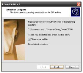
7. On your Desktop, right-click the ScannerDriver_CanonCR180.zip folder and select Extract All.  An extraction wizard opens


8. Click Next to start the wizard.


9. Click Next
Note:  If you want to change the destination of the files, click Browse to select a new location.


10. Select Show extracted files and click Finish to complete the extraction and show the extracted files.


Task 2:  Install the Canon CR-180 Scanner Driver


1. Double-click the setup.exe file to open the Canon CR-180 installation wizard.
2. Wait for the Preparing install screen to finish.
3. Click Next to begin the install process.
4. If you receive a Security Warning, Click Run to continue with the install.
5. Use the Default English language, Click OK.
6. Once the scanner driver install completes Click Finish.

7. Once the Driver Install is completed the Scanner Utility Software install will begin.
8. Click Next to continue with the Utility Install
9. Agree to the license agreement, Click Yes
10. Click Next to agree with the default file location.

11. Click Finish to complete the install.

12. Plug in the scanner and connect it to the computer.  You can then log in to Web Client to register the computer and scanner.


Quick Guide to Canon TC-80N3 Timer/Remote Controller

The TC-80N3 Timer/Remote Controller is a programmable electronic shutter release. When you connect it to your EOS SLR or DSLR it will allow you to control:

1. when the shutter opens (self-timer mode)
2. how frequently the shutter opens (interval timer mode)
3. how long the shutter stays open (long-exposure timer mode)
4. how many exposures the camera will make in total (exposure count mode)

You can also combine modes: For example, you can program the controller to wait five minutes, release the shutter, then take a total of 25 exposures at five minute intervals. Refer to the Combinations Chart for more details.

The TC-80N3 also includes a remote switch that provides the same functions as your camera’s shutter button (auto-focus, autoexposure, and shutter release). When used simply as a remote release (no timer functions), the TC-80N3 does not require battery power. 

Compatible Cameras
• EOS 1v, 1v-HS, and EOS 3 film cameras
• All versions of EOS-1D and EOS-1Ds
• EOS D30 and D60
• EOS 10D, 20D, 30D, 40D, 50D, 7D
• EOS 5D and 5D Mark II

Controls and Functions


Connecting/Disconnecting the TC-80N3
1. Remove your camera’s remote control socket cover and place it in the holder provided on the back of the TC-80N3.
2. Insert the TC-80N3’s plug into your camera’s remote control socket by pressing the round black base of the plug. (Note: Touching the silver collar will prevent the plug from locking.) To remove the plug, grasp the silver collar and pull outward.

Setting a Time Amount
1. Press the Mode Button to select one of the three timing modes (self-timer, interval, or long exposure).
2. Press the Jog Dial to select the time unit you wish to set. Each time you press the dial, the time units will blink in the following order: Seconds → Minutes → Hours, in a continuous loop. When the time unit you wish to set is blinking, turn the Jog Dial to the amount you want.
3.    After setting a time unit, press the Jog Dial once to register it. Time amounts can be set in single digit 
increments, up to:  Seconds: 59 Minutes: 59 Hours: 99
4.   Repeat Step 3 for any additional time units you wish to set. Once a time unit has been registered it will no longer blink.

Self-timer Mode
1.    Use the Jog Dial to set the desired delay time.
2.    Press the Start/Stop button to start the self-timer. The Self-timer icon will start blinking and the time display will count down. The shutter will release when the timer reaches zero (0). To pause the self-timer 
before the shutter releases, press the Start/Stop button. Press it again to resume.
  • Do not use the TC-80N3 in combination with your camera’s self-timer. Doing so may interfere with the TC-80N3's timer function.
  • You can combine the self-timer with the Long Exposure Mode for Bulb exposures. Setting your camera to Bulb will result in a Bulb exposure only if you have set the the TC-80N3 to Long Exposure Mode.
  • If you combine the Long Exposure Mode and Interval Timer Mode, both will begin only after the Self-timer delay has elapsed.
Interval Timer Mode
1.   Use the Jog Dial to set the desired time interval.
2.   Press the Start/Stop button. The camera will immediately take the first exposure. Note: If you want to program a sequence of exposures at a given interval you must set the exposure count to an amount greater than one. Subsequent exposures will be at the interval you have set.
3.  To pause the interval timer, press the Start/Stop button. Press it again to resume. Note: The interval you select must be longer than than the combined time of the shutter speed and shutter recocking time, otherwise the result will be continuous shooting.

When you are shooting with electronic flash the time interval you set must be longer than the flash recycle time. If the time interval is less than the recycle time the shutter will not release until the flash unit has recycled. With Canon Speedlites that have the Save Energy (SE) feature, the flash will automatically recycle 

one minute before the exposure.


Long Exposure Mode
1.    You must set the camera's shutter to Bulb (B), otherwise the camera will shoot continuously until the 
exposure time you have set expires or you run out of exposures, whichever comes first.
2.  Use the Jog Dial to set the desired exposure time.
3.  Press the Start/Stop button. The exposure will start, the icon will blink and the exposure time will begin to count down.
4. To cancel the exposure, press the Start/Stop button. Note: For unattended shooting, focus manually. If the camera is set to AF and is unable to find focus it may not release the shutter. 

Exposure Count
1.   Press the Mode Button to select the Exposure Count mode.

2.   Press the Jog Dial. The exposure count digits will begin to blink.

3. Turn the Jog Dial to the number of exposures you want, from 1 to 99. If you set the counter to 00, the number of exposures will limited only by the amount of film or memory card space available.
4.   Press the Jog Dial to register the number of exposures. Once an amount has been registered the exposure count display will no longer blink.
5.   Press the Start/Stop button. The camera will begin shooting and will continue until it completes the number of exposures


you have. The TC-80N3 will count down the number of exposures. Unless you specify a specific interval, the exposures will be taken at one-second intervals. Note: When shooting a sequence of exposures with flash, set the interval timer so that the flash will have enough time to recyle between exposures.


Hold Function
The Hold function prevents accidental changes to your settings. It also prevents the Start/Stop Button from accidentally stopping an operation after it has started. To activate this function, press and hold the Display Illuminator Button for at least three seconds until the Hold indicator appears on the display. 
To cancel this function, press and hold the Display Illuminator Button for at least three seconds until the Hold indicator disappears. 

Cancelling the Settings
Simultaneously press the Mode Button, Display Illuminator Button and Jog Dial to cancel all settings. Setting the time or number of exposures to 0 will cancel the respective mode. Remote Switch Function The TC-80N3's Release Button functions in the same way as the remote Switch RS-80NC. The remote switch function does not require battery power.


As with your camera's shutter button, you can press the Release Button either halfway or all the way. Pressing it halfway activates your camera's autofocus and exposure meter. Pressing it all the way will release the shutter. For long exposures or continuous shooting, press the Release Button completely and slide it forward, in the direction of the Running Lock Arrow. This will lock the button in the fully depressed position. To release the button, slide it back to its original position.


Note: Even when the Interval Mode or Self-timer are active, you can still take a picture immediately by pressing the Release Button or your camera's shutter button. Also note that the timing or exposure count mode you have set will not be affected if you use the Release Button. During a long exposure that is controlled by the TC-80N3, however, the release button will be inoperable.


Timer Mode Combinations


How to set up Linksys WRT54G as wireless access point only


A few folks asked me this. My main reason was that my Linksys BEFSR41V2 wired
router gave me the opportunity to forward WAN connection log records to Wallwatcher
using SNMP. This feature did not exist on the WRT54G using the standard Linksys
firmware, so I wanted to be able to use the BEF* as my primary router and hang the
WRT54G off it as a wireless access point.

Other reasons why you might want do to this include using the WRT* unit as a wireless
range extender, or to separate wireless clients from a wired router for security reasons.
You also get to use the WRT54G as a switch for the connection of additional wired
devices.

Network


The following diagram shows how I connected the equipment. Note that my WRT54G is
a Version 2 unit. At the time I was using SveaSoft firmware

As you can see, the network contains a mixture of wired and wireless clients. The
DHCP server of the WRT54G is disabled, and its WAN connection is not used. The
BEF* router is the gateway for the LAN and manages the WAN connection. It also
includes static DNS settings from my ISP. You might not need to worry about this, but if
in doubt check with your ISP to find out what you need.

WRT54G configuration

There are other ways to “get there from here”, but this depends on how you are set up
initially. Needless to say, I can’t be responsible for any problems that you might
encounter.

1) Reset the WRT54G to factory defaults

The first thing you will probably need to do will be to “hard reset” the WRT54G to factory
default settings. This WILL destroy any custom router settings, so be sure to make
written notes of these so you will be able to recreate them later.  This is NOT covered in
this document. Refer to your router’s manual and your ISP as may be required.
To reset the router, use a paper clip or something similar to hold down the recessed
switch marked “Reset” for at least twenty seconds.  If in doubt, refer to your router
manual.

2) Connect a computer to the WRT54G
Next, connect a computer to one of the four numbered ports on the back of the router

using a regular Ethernet patch cable. It should be set up to use DHCP to acquire a
dynamic address.

3) Sign in to configure the WRT54G


Now use your web browser to sign in to the configuration web site on the router using
the default gateway address http://192.168.1.1, and the default password “admin”.
Refer to your router manual if you are not sure.

4) Setup/Basic Setup
Setup/Basic Setup options should now be configured as follows:
1. Disable the router’s DHCP server (clients will use the server on the BEF* router
at 192.168.2.254, which is also the gateway).
2. Set a static IP address for the WRT54G itself (I used 192.168.2.253).
3. Set the gateway address.


When you have made your changes, hit the “Save Settings” button at the foot of the
page. The WRT54G will then reboot and you will lose your connection.


5) Rewire the LAN
Now you have to connect the equipment as shown in the “Network” diagram above.

6) Setup/Advanced Routing
The following steps might not be required, but this is what I did to get it working for me.
Configure Setup/Advanced Routing as below.
1. Configure the default route:


2. Route for the LAN:

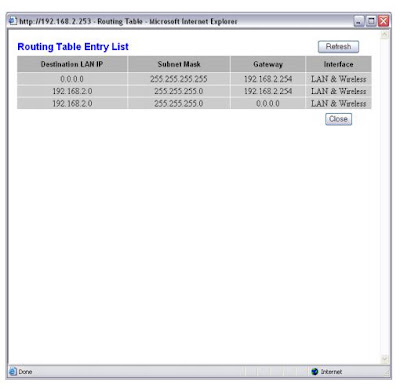
3. The Routing Table now looks like this:


Notes
I wrote up the first version of this document so I’d be able to remember how recreate
the configuration. Since then, the information has proved to be quite popular, so I
updated it and provided additional explanations. If you have any comments or questions
you can e-mail me here: info@michaelcook.ca.

You can check out other HOWTO’s here and various Hints and Tips here.
My other web site is at www.michaelcook.ca.
Right now I am using Sveasoft’s free Alchemy-V1.0 v3.37.6.8svV1.0 v3.37.6.8sv
firmware. See http://www.linksysinfo.org/ for more information on this and other 3
rd party firmware for the WRT54G.


source: http://www.skyprod.net/pub/HowTo/WRT54GWAP/How%20to%20set%20up%20WRT54G.AP.V2.pdf